

Create Drawing is the main A+ Tools command. You pick a curtain wall and a point to look at it from, and A+ builds the full drawing set for that wall: an elevation and a plan, optional schedules, divided glass panels, automatic dimensions, tags, a name taken from the wall's own parameters, and placement on your sheet. All of this comes from one set of saved settings, so every curtain wall in the project is drawn the same way. Use it for type elevations of glazed partitions and curtain walls, or for one drawing per wall instance.
| Where | A+ Tools tab › Curtain Wall panel › Create Drawing |
| You select | One curtain wall, then an observation point (the side you want to see the wall from). With Multiple switched on you can keep going, one wall after another. |
| You get | An elevation view, a plan view, up to three schedules, dimensions, tags, and viewports placed on your target sheet. A new sheet is added to the series when the current one is full. |
| Credits (Free licence) | One charge per curtain wall drawing that is actually created. Currently 15 credits per drawing. See Licensing and credits. |
What you get
Each run creates one drawing set per curtain wall:
Elevation view: a section view looking straight at the wall from the side you picked. It is cropped to the wall, uses the view type and view template you chose, and is named base name + elevation suffix (for example
GP01-elevation). In the Project Browser it appears under the branch for the chosen view type, normally Sections.Plan view: a floor plan on the wall's base level, rotated so the wall runs horizontally across the view. It is cropped around the wall and named base name + plan suffix (for example
GP01-plan).Schedules (optional, up to three): each one is named base name + schedule suffix and filtered so it lists only this wall (see Schedule filters).
Panel division (optional): oversized glass panels are divided to your standard width, or the whole wall is laid out with a repeating custom pattern.
Dimensions on the elevation:
- overall width (top) and overall height (left)
- detailed chains for panel widths (bottom) and panel heights (right)
- a segment chain under the bottom chain that measures each run of panels of the same kind
Optionally, equal widths can be replaced with letters and any dimension can be given text overrides.
Tags on the plan (each one optional): room tags, door tags for the doors in the wall, and a tag for the curtain wall itself.
Sheet placement: the elevation, the plan and the schedules are stacked as one set and placed on your target sheet, using the dynamic, centred or grid layout. If the sheet is full, A+ creates the next sheet in the same number series, with the same title block and sheet properties.
When the run finishes, A+ opens every sheet it used and makes the first one active.
 A typical result: elevation with overall, detailed and segment dimensions, the plan with room and door tags, and a schedule, placed together on the sheet.
Before you start
- Sign in or start a trial. The button is greyed out until an account is signed in or a trial is running. See Getting started.
- Open a model view. The button only works in a floor plan, ceiling plan, structural plan, area plan, elevation, section, detail view or 3D view, because those are the views where you can click a wall. It is greyed out on sheets, schedules, legends and drafting views.
- Have the project content ready. The settings refer to things that must already exist in the project: view templates, view types, dimension types, tag families, the glass curtain panel family, schedule view templates or schedules, and the target sheet. A+ never invents a sheet, so create the sheet (with its title block) first. If your company uses an A+ repository, loading settings from it can bring this content into the project for you. See Settings profiles and repositories.
- Check the wall. Straight curtain walls and single-curved (arc) curtain walls are supported. Double-curved (spline or ellipse based) walls are not.
- First run in a project. If the project has no A+ settings yet, or a setting points to something the project doesn't contain, the Curtain Wall Drawing Settings window opens automatically before you pick anything. Fix the fields shown in red, then click OK.
Step by step
 The Create Drawing button on the Curtain Wall panel.
- Open a plan, elevation, section or 3D view where you can see the curtain wall.
- Click A+ Tools › Curtain Wall › Create Drawing. If the button has become a dropdown, pick a profile (see Running a profile from the ribbon).
- A+ checks your licence and the project's settings. If something is missing, the settings window or a message appears first (see Messages you might see).
- (Optional) Before you pick a wall, use the controls Revit shows for the command (see Options bar):
- Multiple keeps the command running so you can draw several walls in a row.
- Settings opens the Curtain Wall Drawing Settings window.
- The status bar says Select curtain wall (Press Escape to finish). Click a curtain wall. Only curtain walls can be selected. If walls were selected before you started the command, A+ ignores that selection, so you always pick the wall here.
- The status bar says Pick observation point (Press Escape to finish). Click a point on the side of the wall you want to look at. The elevation looks at the wall from that side. With Custom Pattern division, the pattern also starts in the bottom-left corner as seen from this point.
- A+ creates the drawing set and places it on the sheet.
- Single mode (Multiple off): the command finishes, commits the work and opens the sheet.
- Multiple mode: you go straight back to step 5 for the next wall. When you're done, click Finish or press Esc.
Note: once you have picked the first wall, Multiple and Settings are locked for the rest of that run. Settings changes therefore always happen before any drawing work starts.
Running a profile from the ribbon
 When at least one profile is flagged "Add as menu item to ribbon", the button becomes a dropdown.
A profile is a named set of Create Drawing settings saved in the project. When you switch on Add as menu item to ribbon for one or more profiles (in the profile bar at the top of the settings window), the Create Drawing button becomes a dropdown:
- One item per flagged profile. The item has the profile's name and the tooltip "Runs the command with the 'name' profile." Clicking it makes that profile the selected one and runs the command straight away. Up to 20 profiles can appear.
- Settings… (at the bottom, below a separator) opens the Curtain Wall Drawing Settings window. Click OK to save and immediately run the command. Click Cancel to just close.
When no profile is flagged, the plain button comes back. Profiles are stored per project, so the dropdown changes when you switch between projects. If a menu item is out of date (for example after an Undo removed a profile), A+ refreshes the ribbon and asks you to pick again.
Options bar: Multiple, Settings and Finish
 Revit 2026: A+ adds its controls to Revit's Options Bar while the command is running.
While the command runs, A+ adds three controls next to Revit's own command options. They disappear when the command ends.
| Control | What it does |
|---|---|
| Multiple | When ticked, the command keeps asking for the next wall after each drawing, so you can draw a whole batch in one run that is undone in one step. Your choice is remembered until you close Revit, and it is shared with Create Panel Divisions and Redimension Elevation. Multiple mode is only available on paid plans. On a Free licence or trial the checkbox is greyed out. |
| Settings | Opens the Curtain Wall Drawing Settings window for this project. Changes you confirm apply to the walls you pick next. |
| Finish | Ends the run and keeps everything created so far, without asking. |
 Revit 2027: the same controls appear as a panel on the Modify tab (a large Settings button, with Multiple and Finish next to it).
Note: Revit 2027 no longer has the Options Bar strip, so in the 2027 edition the controls appear as a temporary panel on the Modify tab instead.
If the controls don't appear. If A+ can't find a place for the controls (for example after a Revit update changed the window layout), two small fallback buttons appear on the Curtain Wall panel to the right of Create Drawing:
- Settings opens the Settings Manager.
- Multiple: OFF / Multiple: ON toggles multiple mode.
The fallback buttons disappear again as soon as the normal controls can be shown.
Finishing, Esc and Undo
- Esc before anything is drawn ends the command quietly. Nothing is created and no credit is used.
- Esc after one or more drawings (multiple mode) opens Commit Changes?, which shows how many drawing sets you have created and on how many sheets. Choose one of:
- Yes - Commit changes and finish: keep everything.
- No - discard: remove everything this run created.
- Continue: go back to picking walls. Closing the prompt also continues.
- Finish on the Options bar is the same as Yes - Commit changes and finish, without the prompt.
- Undo: a whole run, with all its walls, is a single Create Curtain Wall Drawing step on Revit's undo list.
- Settings are separate. Settings you confirm with OK or Apply, even in the middle of a command, are saved as their own undoable step (Save A+ settings). Cancelling or discarding a drawing run never throws away settings you applied. To revert a settings change, use Undo.
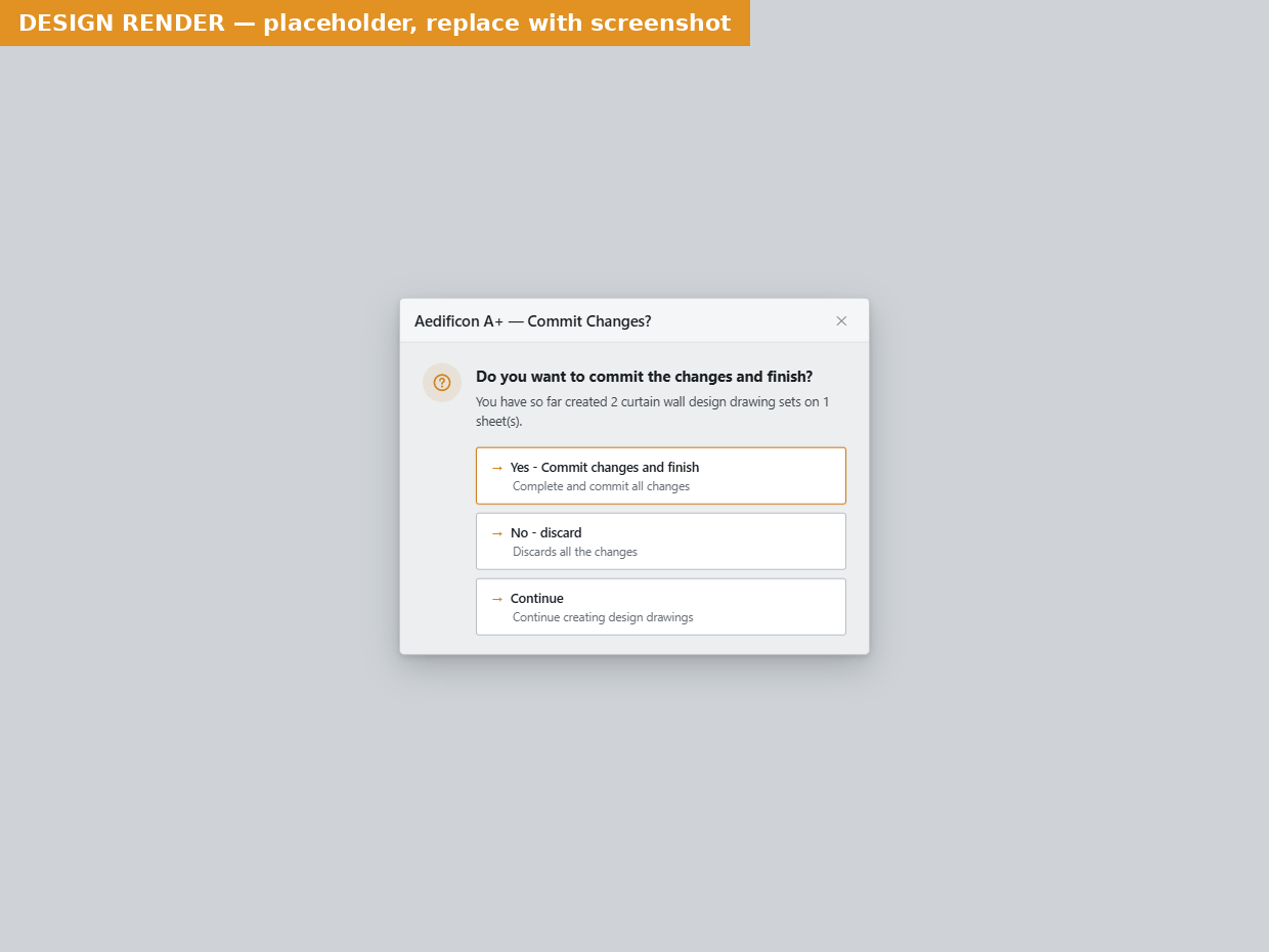 Pressing Esc after drawings have been created in multiple mode.
Settings
All options live in the Curtain Wall Drawing Settings window. You can open it in four ways:
- the Settings control while the command runs
- Settings… in the ribbon dropdown
- the Curtain Wall page of the Settings Manager
- automatically, when the settings aren't valid for the project
Settings are stored in the project as named profiles. They are not stored on your computer, so everyone working in the model shares them.
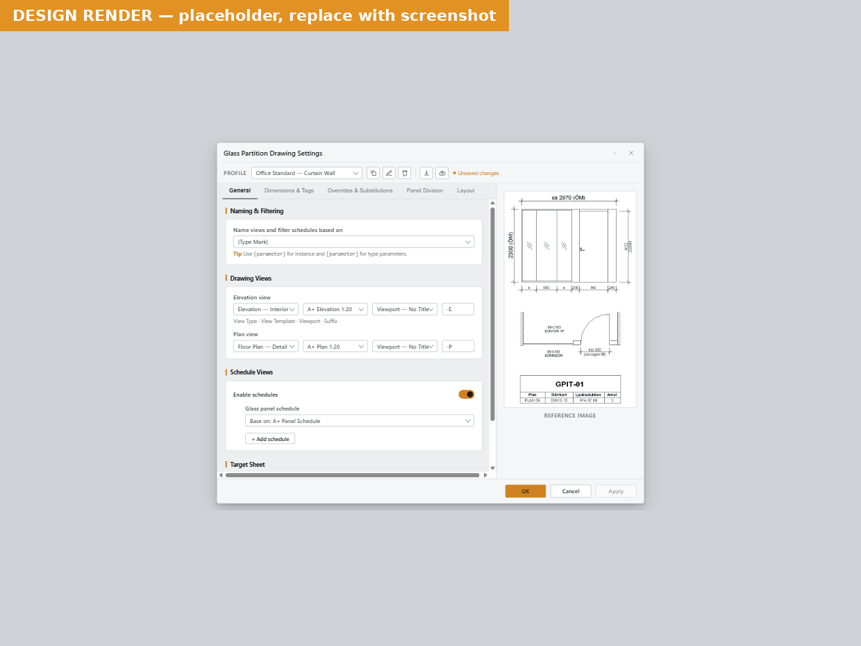 The settings window: profile bar at the top, five tabs, a reference image on the right, and the buttons at the bottom.
Lengths are entered in your project's length units, and every length field shows the unit in its label. The defaults below are given in millimetres.
Profile bar
The band at the top of the window chooses which profile you are editing. From here you can also:
- duplicate, rename or delete a profile
- flag a profile with Add as menu item to ribbon
- Load settings from a repository or another source
- Push to repository… (repository managers only)
An Unsaved changes badge shows when you have edits that are not yet applied. The bar is the same in every A+ settings window. See Settings profiles and repositories.
General tab
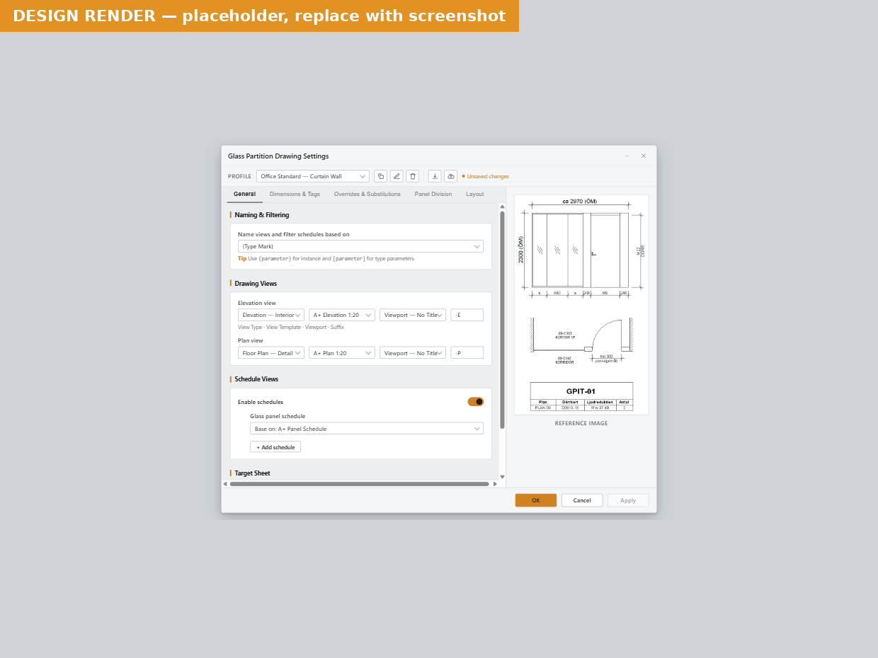 General: how views are named, which view types and templates they use, and which schedules are created.
Naming and Filtering
| Setting | What it does | Default / tip |
|---|---|---|
| Name views and filter schedules based on | The base name pattern. It names every view in the drawing set and supplies the default schedule filter. You can type your own pattern or pick [Type Mark], [Type] or {Mark} from the list. Use {parameter} for instance parameters and [parameter] for type parameters, as the tip under the field says. |
Required. See Naming with parameters for the full token reference and examples. |
Drawing Views
There is one row for the elevation and one for the plan. Each row has four fields:
| Setting | What it does | Default / tip |
|---|---|---|
| Elevation View Type / Plan View Type | The view type for the new view. The elevation lists section view types and detail view types. The plan lists floor plan view types. (default) uses the project's first type of that kind. | (default). Pick a dedicated type (for example "A+ Elevation") so the views get their own Project Browser branch. |
| View Template | The template applied to the new view. (from view type) keeps the template that the chosen view type assigns. (none) applies no template and uses the default scale. Otherwise choose a section template (elevation) or floor plan template (plan). | Required. If either view is set to (none), A+ warns you before each run (View Template Not Configured). The template is where scale, detail level, visibility and phase are set. |
| Viewport type | The viewport type used when the view is placed on the sheet. It controls the view title and extension line. (default) keeps Revit's default viewport type. | (default) |
| Suffix | Text added after the base name to form the view name. It may contain parameter tokens. | -elevation and -plan. Keep the two suffixes different. If a token in a suffix can't be found on the wall, the suffix is left out and that view is created without its view template. |
Schedule Views
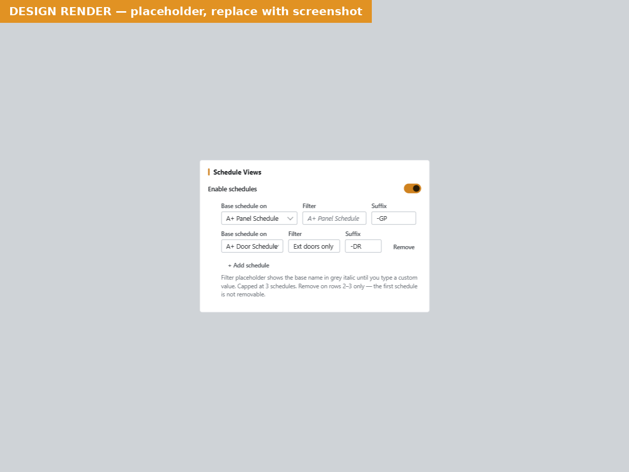 Each schedule row: what to base it on, how to filter it, and its name suffix.
| Setting | What it does | Default / tip |
|---|---|---|
| Enable schedules | Switch on to create schedules with each drawing. When it's off, the rows below are greyed out and no schedules are made. | Off |
| Base Schedule On | What each schedule is made from. Under View Templates: a new wall schedule is created and the schedule view template applied. Under Active Schedules: an existing schedule is duplicated, which keeps its fields, sorting, appearance and column widths. | Required for each row. Use Active Schedules when you want a schedule of another category, or exact column widths. |
| Filter | The value that limits the schedule to this wall. When the box is empty it shows your base-name pattern in grey italics, which means "filter on the base name". Type your own text or tokens to use a custom filter instead. Clear the box to go back to the default. | Empty (base name). See Schedule filters. |
| Suffix | Added to the base name to name the schedule. May contain tokens. | Empty. Only one schedule may have an empty suffix, and the other suffixes must all be different (not case-sensitive). |
| Remove | Deletes this schedule row. The first row can't be removed. | — |
| Add schedule | Adds another row. You can have up to 3 schedules. The button disappears at the limit. | — |
Dimensions & Tags tab
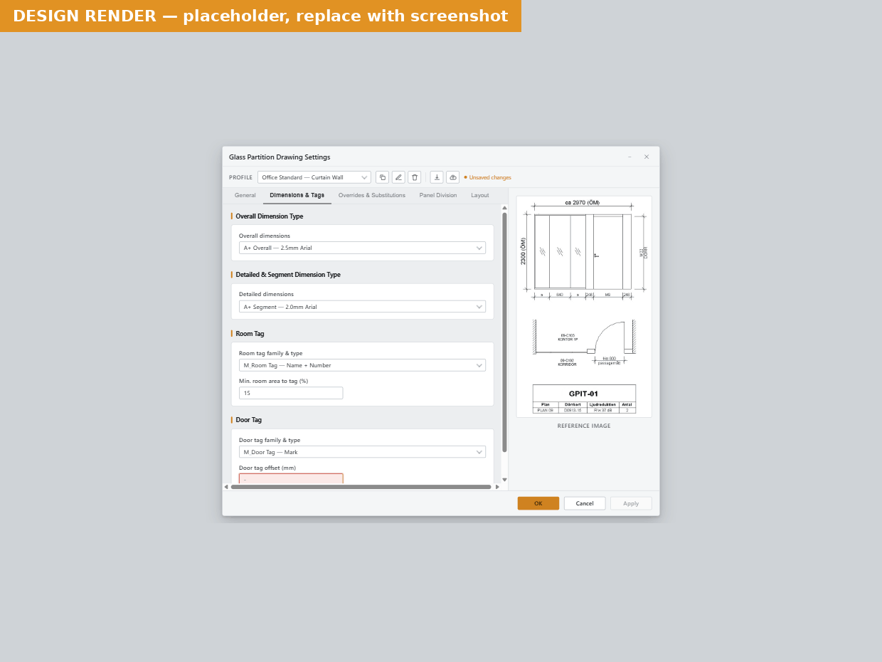 Dimension types and line offsets for the elevation, and the tags placed on the plan.
Dimension Types on Elevation
| Setting | What it does | Default / tip |
|---|---|---|
| Overall Dimensions | The linear dimension type for the overall width (above the wall) and overall height (left of the wall). | Required |
| Dimension line offset (overall) | How far the overall dimension lines sit from the wall edge, measured in the model. | 400 mm. Must be greater than 0. At 1:50, 400 mm in the model is 8 mm on paper. |
| Detailed Dimensions | The dimension type for the chains of individual panel widths (below the wall) and panel heights (right of the wall). | Required |
| Dimension line offset (detailed) | Distance from the wall edge to the detailed chains. | 200 mm. Must be greater than 0. Keep it smaller than the overall offset. |
| Segment Dimensions | The dimension type for the segment chain. This chain measures each run of consecutive panels of the same kind, such as the glass between two doors. | If left empty, the detailed type is used. |
| Dimension line offset (segment) | Distance of the segment chain below the detailed chain. It is added to the detailed offset. | 300 mm, so with the defaults the segment chain sits 500 mm below the wall. Must be greater than 0. |
Note: on a wall whose grid has an angle, only the overall dimensions are created and you are told about it (Detailed Dimensions Skipped).
Tags on Plan
| Setting | What it does | Default / tip |
|---|---|---|
| Curtain Wall Tag Family and Type | A wall tag placed on the plan to tag the curtain wall itself. (none) turns it off. | (none). Pick a type, not a family heading. |
| Vertical offset | Distance (in the model) from the wall's location line down to the top of the tag. The tag lines up with the left edge of the plan's crop. Negative values move it the other way. | 500 mm. A wall that already has a tag in this view isn't tagged again. |
| Room Tag Family and Type | The room tag placed on rooms on the plan's level that are visible in the cropped plan. (none) turns room tagging off. | (none) |
| Room tag offset | Distance on paper from the centre of the room's visible area to its tag, upwards in the view. Negative values move it down. | 0 (the tag sits on the centre) |
| Min. room area to tag (%) | A room is only tagged if its visible part covers at least this percentage of the plan's cropped area. This keeps slivers at the crop edge untagged. | 20. Whole number from 1 to 99. |
| Door Tag Family and Type | The door tag placed on every door panel in the curtain wall, on the plan, without a leader. (none) turns door tagging off. | (none) |
| Door tag offset | Distance on paper from the door to its tag, upwards in the view. Negative values move it down. | 2 mm on paper |
Overrides and Substitutions tab
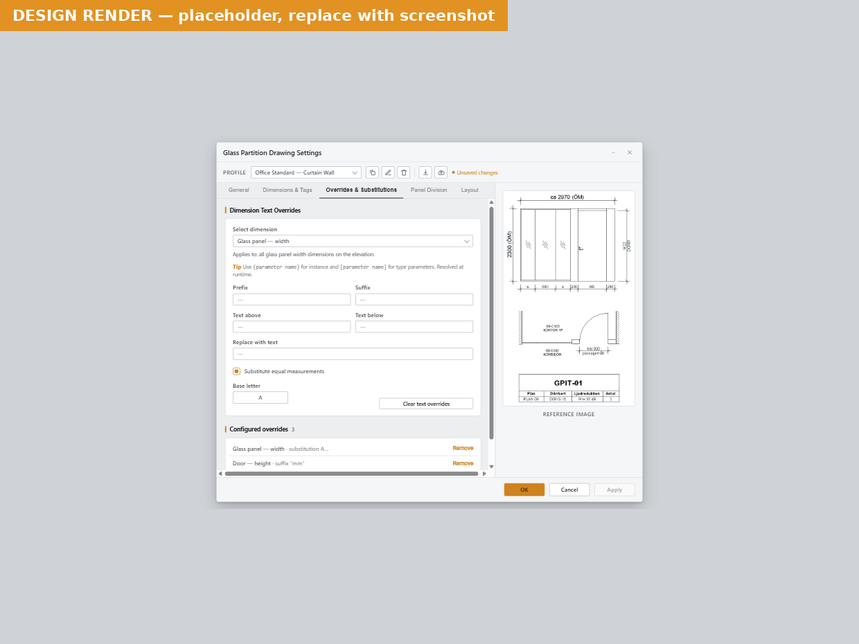 Choose a dimension, type the override text, and check the result in Configured Overrides.
Dimension Text Overrides
First choose a dimension in Select Dimension Type to Override. The list is grouped by these headings:
- Overall Dimensions: Top Dimension, Left Side Dimension, Segment Dimension
- Glass Panel Dimensions: Bottom Dimensions, Right Side Dimensions
- Door Panel Dimensions: Bottom Dimensions, Right Side Dimensions
- All Other Panels: Bottom Dimensions, Right Side Dimensions
A line under the list explains what the selection applies to, for example "Applies to all panels of type: your glass family". Then fill in any of these fields:
| Setting | What it does | Default / tip |
|---|---|---|
| Prefix / Suffix | Text placed before or after the dimension value. | Empty. Greyed out while Replace with text has text. |
| Text above / Text below | Text shown above or below the dimension value. | Empty |
| Replace with text | Replaces the value completely. | Empty. Greyed out while letter substitution is on. |
| Letter substitution › Substitute equal measurements | (Glass, door and other panel rows only) Replaces equal widths with letters. | Off. See Overrides and letter substitution explained. |
| Base letter | The first letter used for substitution. Shared by all panel kinds. | a |
| Clear All Text Overrides | Clears every override and switches off all letter substitution in this profile. | — |
All text fields accept parameter tokens, as the tip in the window says: {parameter name} for instance and [parameter name] for type parameters, resolved at run time. For the overall and segment dimensions they are read from the curtain wall. For the panel rows they are read from each panel, so you can put a door's own mark on its dimension.
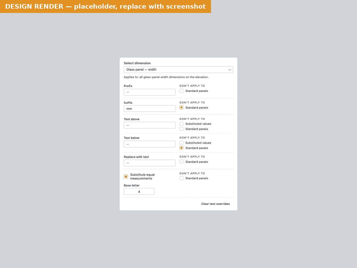 Glass panel rows add a Don't apply to column, so you can exclude standard-width panels or lettered values.
For the Glass Panel rows, each field has a Don't apply to group:
- Standard panels: skip panels whose width equals the Standard panel size on the Panel Division tab.
- Substituted values (Text above and Text below only): skip values that have been replaced by a letter.
Configured Overrides
This panel lists every dimension that has an override or letter substitution in the current profile, with a short summary of each one. For example: Suffix: "mm" (Does not apply to standard panels), or "Equal measurements will be substituted with a letter." Click Remove to clear that entry. When nothing is set, it says No overrides configured.
Panel Division tab
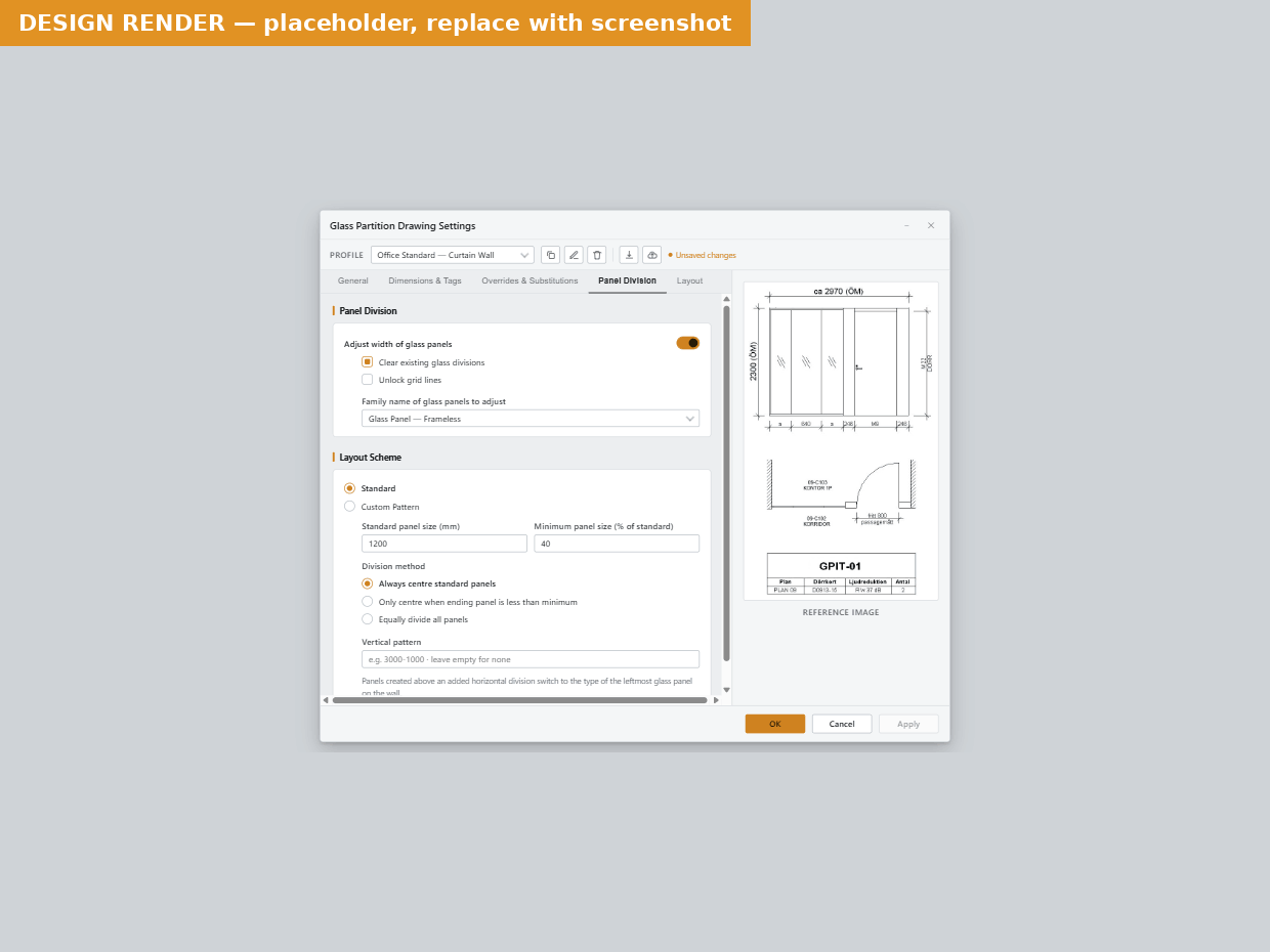 Standard scheme: glass panels wider than the standard size are divided.
| Setting | What it does | Default / tip |
|---|---|---|
| Adjust width of glass panels | Switch on to divide glass panels as part of each drawing. When it's off, everything below is greyed out and the wall's grid is not changed. | Off |
| Clear existing glass divisions | Removes the existing divisions between glass panels first, so the wall is laid out from scratch. Grid lines next to doors are kept. Under Custom Pattern, or when a vertical pattern is set, the horizontal lines are cleared too. | Off |
| Unlock grid lines | When clearing finds locked (pinned) grid lines, unlocks them automatically. When this is off, you are asked each time (Locked Grid Lines). | Off |
| Family name of glass panels to adjust | The curtain panel family that counts as glass. Only panels of this family are divided. The same family decides which dimensions count as "glass" on the Overrides tab. | Required when the switch is on |
Layout Scheme
Choose Standard or Custom Pattern. The selected scheme shows in bold, and only its own fields are shown.
Standard: divides glass panels that are wider than the standard size. Doors and other panels are not touched.
| Setting | What it does | Default / tip |
|---|---|---|
| Standard panel size | The target width that glass panels are divided to. | 800 mm. Must be greater than 0. Also used by letter substitution and the "Standard panels" exclusions. |
| Minimum panel size (% of standard) | The smallest panel allowed, as a percentage of the standard size. | 70. Whole number from 1 to 99. |
| Division method | Always centre standard panels: full standard panels sit in the middle, with two equal end panels. If the end panels would be below the minimum, one standard panel is given up and the width redistributed. Only centre when ending panel is less than minimum: standard panels run from one end and the leftover panel goes at the other end. If that leftover would be below the minimum, the layout is centred instead. Equally divide all panels: every panel gets the same width, none wider than the standard size. |
Always centre standard panels |
| Vertical pattern | Optional horizontal divisions, written as heights separated by dashes and repeated from the bottom up (for example 3000-1000). The leftover goes at the top. |
Empty (no horizontal divisions) |
As the note in the window says, panels created above an added horizontal division are switched to the type of the leftmost glass panel on the wall. For example, the panel above a door becomes glass instead of a copy of the door.
 Custom Pattern: the whole wall is laid out with repeating patterns.
Custom Pattern: lays out the whole wall with repeating patterns. It only applies to walls where every panel belongs to the glass family. Doors are added by hand afterwards.
| Setting | What it does | Default / tip |
|---|---|---|
| Horizontal pattern | Panel widths, repeated across the wall from the bottom-left corner as seen from your observation point. This creates the vertical grid lines. | Empty. See Custom pattern syntax. |
| Vertical pattern | Panel heights, repeated from the bottom up. This creates the horizontal grid lines. | Empty. At least one of the two patterns is required. |
| Pattern placement | Always centre pattern horizontally on curtain wall: the leftover width is split into two equal end panels. Only centre when ending panel is less than minimum: the leftover stays at the far (right) end, and the layout is centred only if that end panel would be too small. |
Always centre |
| Minimum panel width | The smallest acceptable end panel of the horizontal pattern. | 800 mm. Must be greater than 0. |
Important: panel division never runs twice on the same wall in a consecutive run. If you draw a wall that already has drawings, and choose Continue with sequence number, the new drawing is made without dividing panels. Re-dividing a wall that already has dimensions on its grid would cause a flood of Revit reference errors. To re-divide an already drawn wall, use Create Panel Divisions and then Redimension Elevation.
Layout tab
The Layout tab has two sub-tabs: Sheet Layout and View Spacing and Cropping.
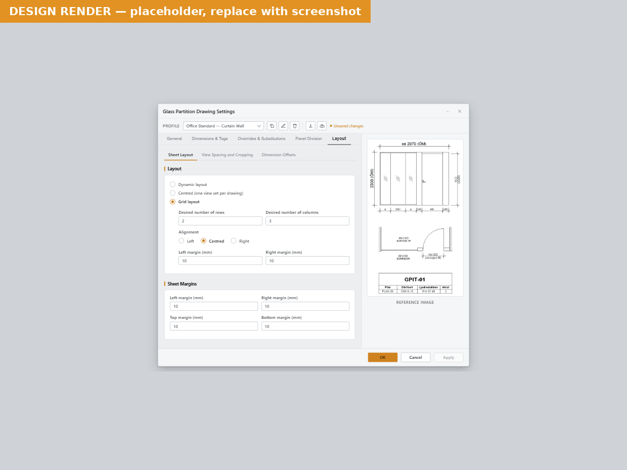 Sheet Layout: target sheet, layout mode and sheet margins.
Sheet Layout
| Setting | What it does | Default / tip |
|---|---|---|
| Add views to sheet (Target Sheet) | The sheet that the drawing sets are placed on. Only existing sheets are listed. As the note says: if there is no more space on the sheet, a new sheet is created in the same number series. | Required. The next sheet gets the next number in the series (for example A101 then A102, or A-01 then A-02), the same sheet name and title block, and copies of the sheet and title block properties. |
| Dynamic layout | Places drawing sets left to right in rows, based on their actual height and width. It fills the space left on a sheet that already has views, and draws a thin dividing line between rows. | Default. Works best on consecutive walls of roughly the same height. |
| Centred (one view set per drawing) | One drawing set per sheet, centred. Each following wall goes on the next sheet in the series. | — |
| Grid layout | Places drawing sets in a fixed grid of cells. A set that is taller than a cell is placed with the dynamic layout instead. | — |
| Desired number of rows / Desired number of columns | (Grid only) The size of the grid. | 2 rows (1–20), 5 columns (1–50) |
| Alignment | (Grid only) Left, Centred or Right: where the grid sits on the sheet. | Centred |
| Left margin / Right margin | (Grid only) Extra space on the aligned side. Left margin is only active with Left, and Right margin only with Right. | 10 mm each |
| Sheet Margins: Left, Right, Top, Bottom margin | The space kept free along each edge of the sheet, for example for the title block strip. Applies to every layout mode. | Left 60, right 140, top 20, bottom 20 mm (on paper) |
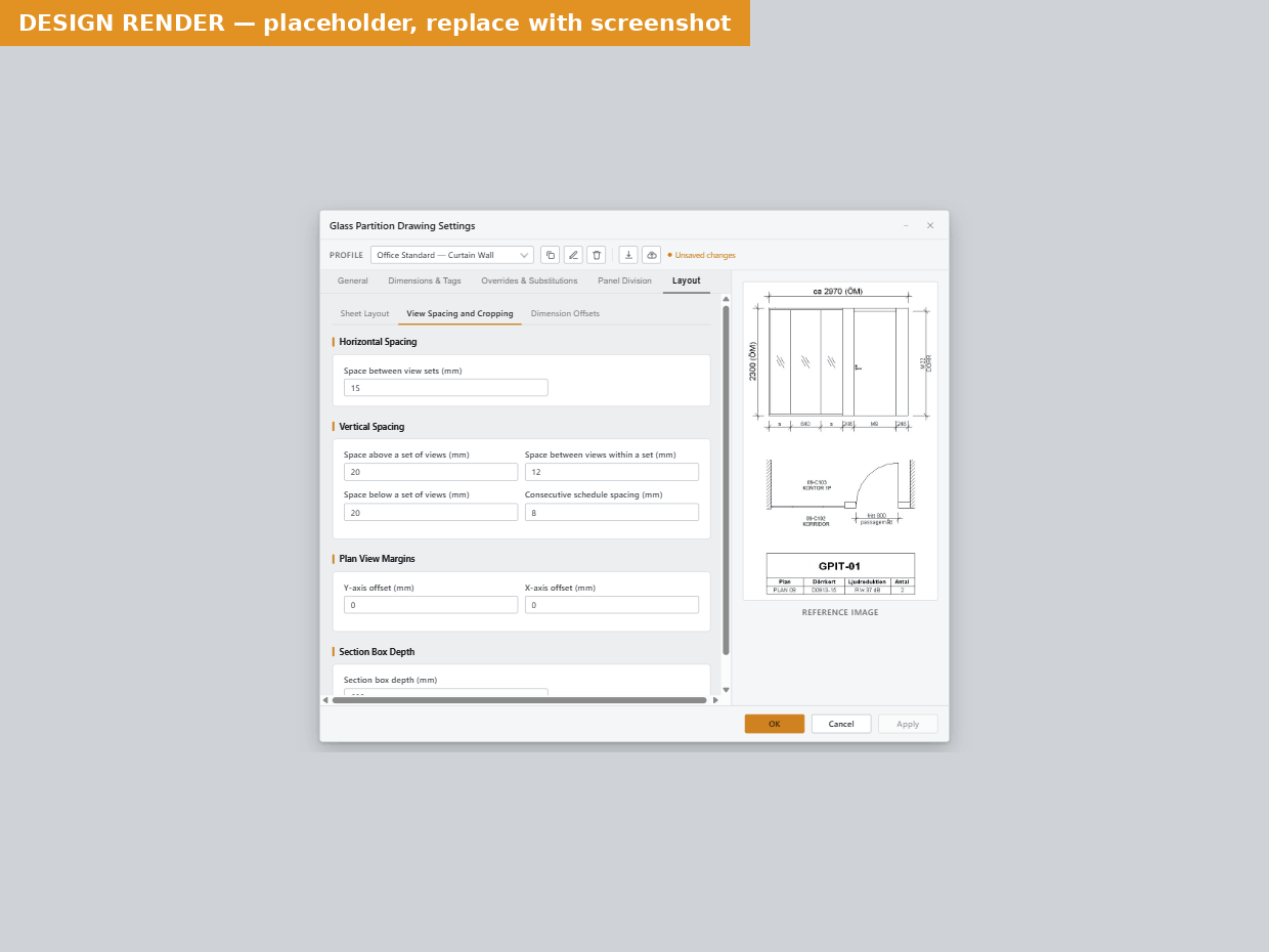 View Spacing and Cropping: spacing on the sheet, the elevation's depth and the plan's crop.
View Spacing and Cropping
| Setting | What it does | Default / tip |
|---|---|---|
| Space between view sets | Horizontal gap on the sheet between two drawing sets. | 50 mm on paper |
| Space above a set of views / Space below a set of views | Extra space above and below each drawing set in a row. | 25 mm each |
| Space between views within a set | Vertical gap between the elevation, the plan and the schedules of one set. | 15 mm |
| Consecutive schedule spacing | Vertical gap between schedules that follow each other in a set. | 2.5 mm |
| Section box depth (Elevation View) | How deep the elevation looks. On a straight wall the depth is centred on the wall. On an arc wall it starts just in front of the wall and is extended by the wall's curvature. | 610 mm in the model. Must be greater than 0. Increase it if mullions or nearby objects are cut off. |
| Y-axis offset (Plan View) | How far the plan's crop extends either side of the wall, across the wall. | 500 mm in the model. Must be greater than 0. Increase it to show more of the rooms. |
| X-axis offset (Plan View) | How far the plan's crop extends past each end of the wall. | 100 mm in the model. Must be greater than 0. |
Tip: the dialog accepts 0 in the offset and depth fields, but the command needs them to be greater than 0 when it runs. With a 0, you get a Configuration Error when you start the command.
Reference image
The right-hand column shows a Reference image: an example of a finished A+ drawing set, with the overall and detailed dimensions, the plan with room and door tags, and a schedule. Use it to see which part of the drawing a setting affects. It is an illustration, not a live preview of your settings.
Buttons, validation and shortcuts
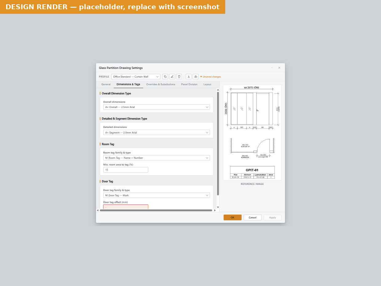 Fields that fail validation turn red, and the tab shows how many problems it has.
| Control | What it does |
|---|---|
| Restore defaults… | Asks Restore default settings? and then loads the A+ default settings into the Default profile, replacing any changes to it. If no local repository with A+ default settings can be loaded, you get a warning and nothing changes. |
| OK | Checks the settings, saves them to the selected profile, and closes. If anything is invalid, a Validation Errors window lists the problems and the window stays open. |
| Cancel | Closes without saving the edits you haven't applied. Anything you already saved with Apply stays saved. |
| Apply | Saves without closing. It is only enabled while there are unsaved changes, the same signal as the Unsaved changes badge. |
| Ctrl+S | Same as Apply, while Apply is enabled. |
| Red fields and tab badges | Fields pointing at something missing from this project, or with an invalid value, are outlined in red. A red number on a tab header shows how many fields on that tab failed. Hover over it for "n setting(s) on this tab did not pass validation". |
The window can be resized. Number fields don't accept letters. Percentage, row and column fields take whole numbers only.
Naming with parameters
The base name is the most important setting. It names the elevation, the plan and every schedule. It is the default schedule filter. It is also how A+ refers to the wall in its messages. It is built from the pattern in Name views and filter schedules based on.
Token reference
| You write | A+ uses | Example result |
|---|---|---|
{Parameter} |
The value of an instance parameter of the picked curtain wall. Built-in, project and shared parameters all work. | {Mark} → A1 |
[Parameter] |
The value of a type parameter of the wall's type. | [Type Mark] → GP01 |
[Type] |
The wall type's name. The older spelling [Type Name] still works. |
[Type] → Glass Partition 2700 |
| Any other text | Kept as typed. | CW-{Mark} → CW-A1 |
- Not case-sensitive:
{mark},{Mark}and{MARK}all find Mark. - Values appear as Revit displays them. Numbers and lengths follow your project's formatting. Parameters that point to another element show that element's name, so
{Base Constraint}gives the level name, for exampleLevel 1. - You can combine as many tokens and as much text as you like, for example
[Type Mark]-{Mark}. - Tokens also work in the view and schedule Suffix fields, the schedule Filter fields, and every dimension text override.
How the names are built
| Item | Name |
|---|---|
| Elevation | base name + elevation suffix → GP01-elevation |
| Plan | base name + plan suffix → GP01-plan |
| Schedule | base name + schedule suffix → GP01 (empty suffix) or GP01-doors |
| Messages during the run | Name the wall by its base name, for example "Detailed dimensions are not supported on 'GP01'…" |
If the name already exists. Before drawing, A+ checks whether a view named base name + elevation suffix already exists. If it does, you get Duplicate View Name, with these choices:
- Continue with sequence number: A+ appends
1,2, … to the base name (for exampleGP01 1-elevationandGP01 1-plan). Panels are not re-divided on that wall. - Cancel
- Stop and commit changes (multiple mode only)
When a parameter is missing or empty
| Situation | What happens |
|---|---|
| The parameter doesn't exist on the wall or its type (often a typo) | The whole base name falls back to the wall type name, the default schedule filter is left empty, and you get Naming Configuration Error: "The parameter could not be found — check that '…' is spelled correctly and exists on the curtain wall or its type." Choose Continue, Commit changes made so far and finish or Cancel. |
| The parameter exists but is empty, and the pattern has no other text | Same fallback, with the message "The parameter '…' exists but has no value on this curtain wall." |
The parameter is empty but the pattern has other text (for example CW-{Mark}) |
No warning. The empty part is simply left out, so the name becomes CW-. Make sure every wall has a value. |
| A token in a suffix can't be found | The suffix is left out, and that view (or schedule) is created without its view template, at the default scale. |
Worked examples
These examples use a wall with Mark = A1 and Base Constraint = Level 1, whose type is called Glass Partition 2700 and has Type Mark = GP01. The suffixes are left at their defaults.
| Pattern | Base name | Elevation / plan | Default schedule filter |
|---|---|---|---|
[Type Mark] |
GP01 |
GP01-elevation / GP01-plan |
Type Mark = GP01 ✓ |
{Mark} |
A1 |
A1-elevation / A1-plan |
Mark = A1 ✓ |
[Type] |
Glass Partition 2700 |
Glass Partition 2700-elevation |
Type = Glass Partition 2700 ✓ |
[Type Mark]-{Mark} |
GP01-A1 |
GP01-A1-elevation |
Type Mark = GP01-A1 ✗ (no wall matches). Set the schedule Filter to [Type Mark] or {Mark}. |
{Base Constraint} {Mark} |
Level 1 A1 |
Level 1 A1-elevation |
Base Constraint = Level 1 A1 ✗. Set the Filter to {Mark}. |
{Elevation ID} (a shared instance parameter you added to walls) |
whatever you typed in it, for example E-12 |
E-12-elevation |
Elevation ID = E-12 ✓, as long as the parameter is available in the schedule |
Tip: choose the token by what one drawing represents. Use
[Type Mark]or[Type]for type drawings: one sheet per wall type, which is what the reference image shows. Any other wall of the same type then triggers the duplicate-name prompt. Use{Mark}or your own instance parameter for one drawing per wall.
Tip: for full control, add a project or shared instance parameter to walls (for example "Elevation ID") and use
{Elevation ID}as the pattern. You decide every name in the model, and a schedule can filter on the same parameter.
Important: always include at least one token. A pattern of plain text only (for example
Partition) gives every wall the same name. With schedules enabled, A+ also has no parameter to filter on, and the drawing fails when it creates the schedule.
Tip: keep names unique. If two walls give the same base name, the second one gets the Duplicate View Name prompt, and continuing creates
… 1names without panel division.
Schedule filters
Each schedule A+ creates gets one equals filter, so that it lists only the wall you drew. A+ works out the filter like this:
- The field. With the default (empty) filter, the field is the first type token in your naming pattern, or the first instance token if there is no type token.
[Type Mark]filters on Type Mark,{Mark}filters on Mark, and[Type]filters on the wall's Type. - The value. With the default filter, the value is the whole base name. That's why the default only works when the pattern is a single token. If you add text or a second token, also fill in the Filter box.
- A custom filter (anything typed in the Filter box) is resolved like the naming pattern. If it contains a token, that token sets the field. If it is plain text, the field from the naming pattern is filtered on that text.
- If the custom filter can't be resolved (missing or empty parameter), A+ falls back to the default and tells you (Schedule Filter Configuration Error).
- If the naming parameter itself is missing, the filter value is left empty. A+ then filters the field that the schedule base already filters on, with an empty value, so the schedule shows (almost) nothing instead of every wall in the project. If the base has no filter at all, the schedule is left unfiltered.
How the filter combines with the schedule you based it on:
- A filter that the base template or schedule already has on the same field is replaced with A+'s per-wall value.
- Filters on other fields are kept as extra conditions.
- The field is added to the schedule if it isn't there already.
- If the base filters on a different field than the one A+ will set, you get Schedule Filter Mismatch before the drawing is made. You can continue anyway, or cancel and fix the template or pattern.
Suffix rule. Each schedule is named base name + suffix. Only one schedule may have an empty suffix, and the others need different suffixes, for example -panels and -doors.
Tip: build one schedule view template per schedule kind, with a filter on the same parameter your naming pattern uses (for example Type Mark equals …). A+ then simply swaps in the value for each wall, and the mismatch warning never appears.
Custom pattern syntax
The Vertical pattern (both schemes) and the Horizontal pattern (Custom Pattern) use the same simple format:
- Sizes are written in your project's length units, separated by dashes:
400-1200-800. A semicolon or a space also works as a separator. - Decimals use your Windows decimal separator, for example
612.5. - Every size must be greater than 0. An empty box means "no divisions in this direction".
- The pattern repeats until the wall is used up.
| Pattern | Direction | What you get |
|---|---|---|
1200 |
Horizontal | Equal 1200 mm bays across the wall. |
400-1200-800 |
Horizontal | Bays of 400, 1200, 800, 400, 1200, 800 … from the bottom-left corner as seen from your observation point. On a 4800 mm wall the pattern fits exactly twice, with no end panels. |
3000-1000 |
Vertical | On a 5000 mm high wall: horizontal lines at 3000 and 4000 mm from the base, leaving a 1000 mm top panel. The leftover always goes at the top. |
900 |
Vertical (Standard scheme) | A transom every 900 mm. The glass panels above the first line take the type of the leftmost glass panel. |
The vertical pattern is measured from the base of the wall, including the bottom mullion.
When the horizontal pattern doesn't fit exactly, Pattern placement decides where the leftover goes. Either it is split into two equal end panels, giving up trailing bays when an end panel would be smaller than the Minimum panel width, or it is kept as one panel at the far end.
Under Custom Pattern, a wall where not every panel belongs to the glass family is skipped. You see Custom Pattern Not Applied straight away, or in a summary at the end of a multiple run. The rest of the drawing is still created.
Overrides and letter substitution explained
Letter substitution makes an elevation easier to read. Equal panel widths are replaced with letters (a, b, c, …) instead of repeating the same number.
- It works per panel kind: Glass Panel, Door Panel and All Other Panels each have their own Substitute equal measurements switch.
- Only widths that occur two or more times get a letter. A width that occurs once keeps its number.
- Panels of the Standard panel size always keep their number, so the standard width reads as a dimension and the odd sizes as letters.
- Letters start at the Base letter (default
a). Each panel kind starts again from the base letter. - Values within 1 mm of each other count as equal.
- On a wall with several rows of panels, only the bottom row of full-height panels is lettered (low strips along the floor are skipped), so the letters describe what you read at floor level.
- While substitution is on for a row, Replace with text is greyed out for it.
Example: a wall of glass panels 800 - 650 - 650 - 800 - 1040 (door) - 800, with a standard size of 800 and glass substitution on, gets a bottom chain reading 800 - a - a - 800 - 1040 - 800. Then:
- adding the suffix
mmwith Don't apply to › Standard panels ticked puts "mm" only on the non-standard glass values - the door's Text below set to
{Mark}shows each door's own mark under its width
Text override fields:
- Prefix and Suffix frame the value, for example
ca+ 2970 givesca 2970. - Text above and Text below add a line over or under it, for example
(ÖM)orGLASS. - Replace with text swaps the value completely, for example
VARIES.
A good use for the overall dimensions is to mark them as approximate: set the Top Dimension prefix to ca and the Text below to (ÖM), as in the reference image.
Tips
- One profile per wall family, on the ribbon. Create profiles such as "Glazed partitions 1:50" and "Facade 1:100", each with its own templates, dimension types and naming, and switch on Add as menu item to ribbon. Your team then picks the right setup straight from the Create Drawing dropdown, with no settings window needed.
- Let view templates do the styling. Scale, detail level, visibility, phase and crop region visibility belong in the elevation and plan view templates. Avoid (none): it uses the default scale and triggers a warning on every run.
- Use dedicated view types. A separate section type and floor plan type for A+ views keeps them together in the Project Browser and lets each type assign its own template (choose (from view type)).
- Prepare the sheet once. Create the first sheet of the series with the right title block and number (for example
A400). A+ fills it and continues withA401,A402… with the same title block and properties. - Batch runs (paid plans). Switch on Multiple, pick wall, point, wall, point … and click Finish. The whole batch is one undo step, and the dynamic layout packs the sets row by row.
- Draw walls of similar height together. The dynamic layout works best when consecutive walls are roughly the same height. For mixed heights, try Grid layout.
- Pick the observation point from the "front". The elevation looks at the wall from that side, and the custom pattern starts in the bottom-left corner as seen from there. In a plan view, click a little way in front of the wall on the room side you want to show.
- Base the schedule on an existing schedule when you need exact column widths, a different category (for example curtain panels), or formatting that a template can't carry. A+ duplicates it for each wall.
- Check the plan crop before a big batch. If room tags are missing, the room's visible part is probably below Min. room area to tag (%) of the crop. Increase the Y-axis offset or lower the percentage.
- Repeat a wall without re-dividing. A consecutive run of the same wall never re-divides panels, so re-running is safe for the grid. Use Redimension Elevation to refresh dimensions on an existing elevation instead of creating new drawings.
- Share settings through a repository. Push a tested profile to your company repository so new projects start with the same setup. See Transfer Settings and Settings profiles and repositories.
- Free licence or trial: you are charged once per drawing, and only after it has been created. Cancelling, pressing Esc before a drawing exists, or changing settings costs nothing.
Messages you might see
This is a short list. For more detail and other messages, see Messages and troubleshooting.
| Message | What it means | What to do |
|---|---|---|
| Unsupported Curtain Wall | The wall is double-curved (spline or ellipse). | Pick a straight or arc curtain wall. |
| Configuration Error: "The following settings are invalid for this document" | A setting points to something this project lacks, even after the settings window was shown. | Open the settings, fix the red fields, or load the profile from your repository. |
| Configuration Error: "Plugin configuration errors" | A value is out of range, for example a 0 offset. | Correct the listed values in the settings window. |
| View Template Not Configured | The elevation or plan template is set to (none). | Yes - Continue anyway, or No - Open configuration. |
| Naming Configuration Error | The naming parameter is missing or empty on this wall. | Check the spelling or fill in the parameter. See Naming with parameters. |
| Schedule Filter Mismatch | The schedule base filters on a different field than A+ will set. | Align the template's filter with your naming pattern, or set a custom Filter. |
| Schedule Filter Configuration Error | A custom schedule filter couldn't be resolved for this wall. | Check the parameter in the Filter box. |
| Duplicate View Name | An elevation with this name already exists. | Continue with sequence number (no panel division), Stop and commit changes or Cancel. |
| Commit Changes? | You pressed Esc after drawings were created. | Commit, discard or continue. See Finishing, Esc and Undo. |
| Locked Grid Lines | Clearing divisions found locked grid lines. | Unlock and continue, Skip dividing or Cancel. Tick Apply to all consecutive curtain walls to stop being asked again in this run. |
| Panel Division Skipped: "Panel redivision is not supported" | The wall's grid has an angle or a layout set on its type. | The drawing is still made without division. Adjust the grid if you need division. |
| Panel Division Skipped: "Custom Pattern Not Applied" | Not every panel belongs to the glass family. | Make all panels glass, or use the Standard scheme. |
| Detailed Dimensions Skipped | The grid is angled, so only overall dimensions were made. | Add detailed dimensions by hand if needed. |
| This project requires a newer version of A+ Tools. | The project's A+ settings were saved by a newer plugin. | Update A+ Tools. |
| Sign-in, licence or credit messages | No active session, credits used up, or no connection. | See Licensing and credits. |
Related pages
- Getting started
- Create Panel Divisions: divide panels on an existing wall without making a drawing
- Redimension Elevation: redo the dimensions on an existing elevation
- Settings Manager
- Settings profiles and repositories
- Transfer Settings
- Licensing and credits
- Messages and troubleshooting
Last updated 2026-10-02.